
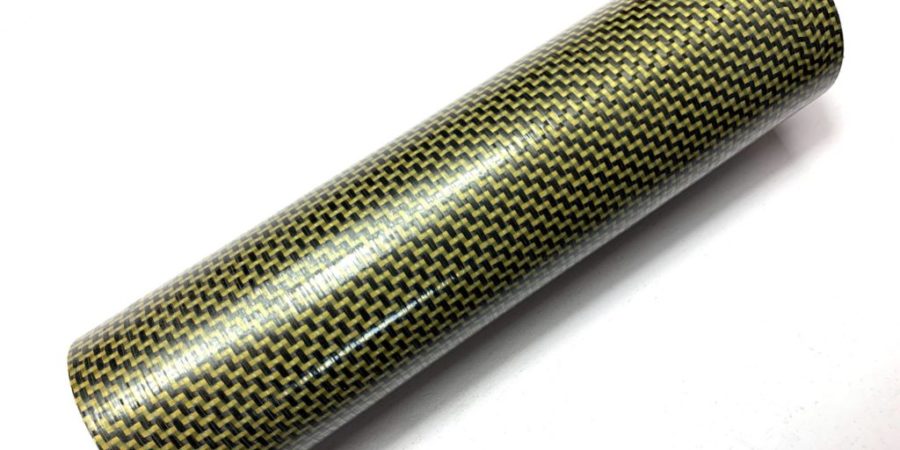
Custom carbon fibre tubes can be manufactured around defined dimensions, loads, movement limits and assembly requirements. The process starts by establishing what the tube must do and where forces enter it.
At Advanced Composites Engineering, the application comes first. Where will the tube bend, twist, clamp or connect? Which diameter controls the fit? These answers help determine its geometry, fibre direction, reinforcement and finish.
Can Carbon Fibre Tubes Be Made to Exact Requirements?
A custom carbon fibre tube can be developed around specified dimensions and performance targets, but “exact” must first be translated into measurable requirements.
A useful specification should identify:
- The dimension or surface controlling the fit
- The permitted dimensional variation
- The expected loads
- The maximum acceptable movement
- The working environment
- The inspection method
Not every combination of diameter, wall thickness, length and tolerance suits the same manufacturing process. Reviewing the complete requirement early helps avoid a tube that matches one dimension but does not fit or perform as intended.
When Is a Custom Tube Better Than a Standard Tube?
A standard tube may be the most practical choice when an available size and construction already meet the application. Custom manufacture becomes useful when the project needs more control over fit, stiffness, movement, connections or finish.
| Requirement | A standard tube may be enough when | Custom manufacture may help when |
| Dimensions | An available diameter and length fit | The tube must match existing components or a defined taper |
| Loading | Loads are relatively simple | Bending, twisting, compression or impact interact |
| Movement | The stiffness of a stock tube is acceptable | Movement must remain within a specified limit |
| Connections | No specialist connections are required | Holes, joints, clamps or inserts need reinforcement |
| Finish | A standard finish is suitable | Bonding, grip, colour or appearance matters |
What Can Be Customised in a Carbon Fibre Tube?
A custom or bespoke carbon fibre tube can be changed across its geometry, internal construction, materials, reinforcement, connections and finish.
| Area | What can change | Why it matters |
| Geometry | Internal diameter, external diameter, length, wall thickness and taper | Controls fit, available space and section stiffness |
| Construction | Layer count and fibre direction | Influences bending, twisting and compression |
| Reinforcement | Extra material at selected positions | Supports joints, clamps, inserts and machined areas |
| Materials | Carbon, glass, aramid or mixed constructions | Balances stiffness, impact behaviour, electrical needs, wear and cost |
| Resin and protection | Resin system, coating or protective finish | Supports suitability for the working environment |
| Connections | Holes, inserts, bonded areas and cut features | Affects assembly and local load transfer |
| Finish | Smooth, painted, visible weave or bond-ready | Supports appearance, grip or later assembly |
Six Decisions That Shape a Custom Carbon Fibre Tube
The most useful starting point is a clear description of the application, the loads involved and the way the tube connects to the surrounding assembly.
1. Loads, Supports and Permitted Movement
We need to understand how the tube is supported, where forces enter it and whether the load bends, twists, pulls or compresses the component.
It is also important to distinguish between strength, stiffness and deflection.
| Term | What it means |
| Strength | Whether the tube can carry the load without failing |
| Stiffness | How strongly the tube resists movement |
| Deflection | How far the tube moves under load |
A tube may survive the expected load but still flex too far for the product to work correctly.
For example, an extension pole may need limited bending, while a rotating shaft may require greater resistance to twisting. Both components could share the same dimensions but need different internal constructions.
2. Dimensions, Fit and Tolerances
The achievable tolerance depends on the tube size, wall construction, tooling, manufacturing process and the surface controlling the fit.
A diameter requirement is incomplete unless it states whether the internal or external surface is critical. Depending on the application, the drawing may also need to define:
- Internal diameter
- External diameter
- Wall thickness
- Overall length
- Taper
- Straightness
- Roundness
- Hole position
- Fit with adjoining components
Tighter tolerances are not automatically better. Restrictive limits may require different tooling, more finishing or additional inspection without improving the finished assembly.
The specification should explain what the surrounding components can accept, which surface controls the interface and how the dimension will be checked.
Unsure How to Specify Your Requirements?
Share your drawing, dimensions or assembly requirements with us. We can help identify the critical tolerances, tooling considerations and information needed to move the project forward.
Discuss Your Project Specification
3. Fibre Direction and Tube Behaviour
Carbon fibre carries load most effectively along the direction of its fibres. Changing the fibre direction changes how the tube responds to bending, twisting and local pressure.
| Fibre direction | Primarily supports |
| Along the tube | Lengthwise loads and bending stiffness |
| At an angle | Twisting and shear |
| Around the circumference | Resistance to splitting and local crushing |
Most custom carbon fibre tubes face more than one type of force, so their construction may combine several fibre directions.
A tube designed mainly for bending should not automatically use the same arrangement as one exposed to repeated twisting, even when their external dimensions are identical.
Unless you already have a validated design, you do not need to provide a finished fibre arrangement. Describe the loads, permitted movement, dimensions, connections and working conditions instead.
4. Materials and Local Reinforcement
Carbon fibre often suits applications where low weight and stiffness are priorities, but it is not the only material we can use.
Depending on the application, a construction may use:
- Carbon fibre
- Glass fibre
- Aramid fibre
- A combination of materials
These options can help balance stiffness, impact behaviour, electrical requirements, wear and cost.
Reinforcement can also be concentrated at the points where it is needed most, including:
- Tube ends
- Clamp positions
- Joints
- Insert locations
- Machined features
- Impact zones
Making the entire tube thicker is not always the most efficient solution. Local reinforcement places material where it performs a defined job and avoids unnecessary weight elsewhere.
5. Working Environment and Surface Requirements
The operating environment can affect the tube’s materials, resin system, protection and finish.
| Consider | Define |
| Temperature | Normal operating and peak conditions |
| Moisture or saltwater | Type, duration and frequency of exposure |
| Chemicals | Substance and level of contact |
| Sunlight | Whether exposure is continuous or occasional |
| Abrasion | Contact, sliding or handling conditions |
| Electrical requirements | Whether conductivity or insulation matters |
| Surface use | Bonding, clamping, sliding, grip or appearance |
It is also useful to explain whether the tube will be cleaned regularly, repeatedly assembled or exposed during storage and transport.
6. Joints, Inserts and Clamps
Inserts, bonded fittings, clamps and telescopic joints introduce load into relatively small areas. Adding these features after the main tube has been designed may cut fibres or create an unreinforced load-entry point. They should therefore be identified before the tube construction is finalised.
Define before manufacture:
- Where the tube is supported
- Where loads enter the tube
- Where holes or inserts will be positioned
- Which surfaces must bond
- Which surfaces must slide
- Which areas will be clamped
- Where local reinforcement may be required
How Manufacturing Choices Affect the Finished Tube
Once the application is defined, we can determine the most suitable manufacturing, tooling and inspection approach.
Roll-Wrapped Tube Construction
At ACE, we manufacture many custom composite tubes by roll wrapping fibre layers around a mandrel, which forms the internal geometry. Fibre directions and local reinforcement can be adjusted to suit loads, tapers and connection points.
Tooling and Inspection
We hold tooling across a range of sizes, although new tooling may be needed for a specific internal diameter, shape or taper.
Before production, agree the dimensions that control fit and performance. These may include diameter, length, straightness, roundness, taper, hole position and fit with adjoining components.
Explore Your Carbon Fibre Tube Options
Review our available carbon fibre tube sizes, wall thicknesses, tapers, reinforcement options and finishes to see what may suit your application.
Is Your Project Ready for an Initial Discussion?
An initial discussion becomes useful once you can explain the tube’s purpose and provide the main requirements already known.
Try to include:
- The intended application
- Critical dimensions
- Principal loads
- Maximum permitted movement
- Support and connection points
- Working conditions
- Expected quantity
You do not need every technical answer or a completed fibre arrangement. A drawing, CAD model, existing component, sample or clear sketch can communicate the confirmed requirements and identify the remaining unknowns.
Ready to Discuss Your Custom Tube Project?
A custom carbon fibre tube should be developed around the work it must perform, not selected from dimensions alone.
Send us your custom carbon fibre drawing (if any), application details, load information, critical dimensions, connection points or initial requirements. You do not need a completed fibre arrangement or final specification to start the conversation.
We can help identify the manufacturing considerations that need to be resolved and determine the appropriate next step for your project. Call our composite specialists on 01670 335490 to discuss your requirements directly with our engineering team.
Frequently Asked Questions
Can an Existing Metal Tube Be Copied in Carbon Fibre?
Its dimensions provide a useful starting point, but a direct copy may not use composite materials effectively. Share the current component, its loads, supports, connections and the reason for replacing it. The carbon fibre tube can then be considered around the actual performance requirement rather than simply reproducing the geometry of a different material.
Does Every Custom Tube Need New Tooling?
Not always. At ACE we hold existing tooling across a range of sizes. New tooling may be required when the necessary internal diameter, shape or taper is unavailable. Tooling should therefore be discussed before finalising dimensions, costs and project timescales.
Can One Tube Construction Be Used at Several Lengths?
Not automatically. A longer tube can bend further under the same load, even when its diameter and wall construction remain unchanged. Each length should be checked against its support points, load position and permitted movement.
Does a Visible Carbon Weave Make the Tube Stronger?
Not necessarily. A visible woven layer may be selected mainly for appearance. Structural performance depends on the complete tube construction, including the direction and position of the fibres carrying the load.
What Happens if the Surrounding Assembly Changes Later?
Changes to adjoining components can affect diameters, tolerances, holes, joints, reinforcement and tooling. Raise changes as early as possible. A relatively small adjustment to the surrounding assembly may require a more substantial change to the tube construction once tooling or production planning has started.