
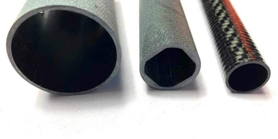
Replacing aluminium with carbon fibre makes engineering sense when the change solves a measurable problem in the wider system. If weight, movement under load, thermal movement, repeated loading, corrosion or the inertia of a moving part is holding performance back, carbon fibre reinforced polymer (CFRP) is worth investigating.
That does not make CFRP an automatic upgrade. Every useful carbon fibre vs aluminium decision we work through starts with what the component has to do, then asks whether a purpose-designed composite can do it well enough to justify the redesign, manufacture and testing involved.
When Does Replacing Aluminium with Carbon Fibre Make Engineering Sense?
An aluminium component becomes a credible CFRP candidate when its material or design is holding back something with measurable value at system level. The trigger might be weight, movement under load, dynamic response, dimensional stability, repeated loading or the environment it works in. Each is a reason to investigate CFRP, not a reason to select it.
Strong reasons to investigate CFRP
- Mass is limiting system performance: Lower mass matters when it changes payload, moving inertia, energy use, handling, or the loads other parts of the system have to carry.
- Deflection is becoming the constraint: The component carries its design load, yet still moves too far to hold the accuracy or alignment required. That movement under load is deflection.
- Moving mass limits dynamics: Robotic arms, gantries and other moving structures can benefit when a lighter component accelerates, stops and settles more quickly.
- Thermal movement affects precision: Materials grow and shrink with temperature. A CFRP laminate can be designed to move differently from aluminium where dimensional stability matters.
- Fatigue or cyclic loading is significant: Repeated loading wears structures out over time. How CFRP copes depends on the laminate, joints, load pattern and environment, so it needs assessing application by application.
- Environmental exposure creates maintenance problems: Carbon fibre does not corrode the way metal does, although the resin around it and any carbon-to-metal joints still need attention.
Start With the Performance Bottleneck
Before comparing material data, define what the aluminium component is no longer doing well enough. That shifts the discussion from ‘which material has the better properties?’ to ‘which design approach best meets the requirement?’
Is the component strength-limited or stiffness-limited?
Breaking and bending are two different problems. A beam, arm or tube can be strong enough to survive its loads and still move too far under bending or twisting. The load it can carry and the movement it is allowed, its allowable deflection, are separate requirements.
For conventional structural design, aluminium behaves much the same in every direction. CFRP does not. Its stiffness depends on the fibre, the direction the fibres run, how the layers are built up and the finished geometry.
What does reducing mass actually change?
Carbon fibre is less dense than aluminium, but that alone does not tell you what the finished component will weigh. Geometry, laminate thickness, buckling, joints and design margins all affect the result.
A better question is what lower mass would change:
- payload
- moving inertia
- acceleration
- energy demand
- handling
- loads elsewhere in the assembly
What loads and allowable deflections govern the design?
Map the real load case, including bending, torsion, compression, shear, the concentrated pressure where fixings grip, known as local bearing, and any loading that changes as the part moves. Include how the component is supported, how far it is allowed to move, and any risk of a thin wall folding under compression, known as buckling.
Is This Aluminium Component a Good Candidate for Carbon Fibre?
The aluminium components we convert successfully tend to share three things. A clear performance constraint, a load path that is understood, and joints and interfaces that can be reconsidered if the composite design calls for it.
| Requirement | Carbon Fibre | Aluminium |
| Weight | Lower mass improves payload, inertia, energy use, handling or another system requirement | Mass has little influence on system performance |
| Stiffness/deflection | The same stiffness is needed at lower weight, or the aluminium section is becoming impractically large | The aluminium design already keeps movement within limits at sensible cost |
| Load direction | The dominant load paths are understood and can shape the fibre layout | Loads are poorly characterised, or it helps that aluminium behaves the same in every direction |
| Fatigue | Repeated loading drives the design, and the structure can be validated against its real load pattern | Other risks such as impact or joint behaviour dominate |
| Environment | Moisture, salt or chemicals make corrosion or maintenance a genuine cost | Existing material protection already meets the service requirement |
| Thermal stability | Movement with temperature affects alignment or precision | Thermal movement is acceptable or easily accommodated |
| Thermal conductivity | Structural efficiency matters more than moving heat through the component | Heat transfer is part of the component’s function |
| Vibration/dynamics | Moving mass, natural frequency or settling behaviour limits performance | Dynamic behaviour already meets the requirement |
| Impact/damage | Impact threats are understood, and damage tolerance can be designed in and inspected | Impacts are unpredictable, or the metal bending rather than breaking is central to the requirement |
| Joining | Joints can be redesigned around suitable bonds, inserts, fasteners and added reinforcement | Existing welded or heavily machined interfaces must stay largely unchanged |
| Manufacturing/economics | Performance or lifecycle value justifies the engineering, tooling and validation | A mature aluminium process already meets the brief at acceptable cost |
Why a Carbon Fibre Replacement Should Be Redesigned
The biggest mistake we see in an aluminium-to-carbon-fibre conversion is treating the existing metal geometry as the specification.
Preserve the functional requirement, not necessarily the aluminium geometry.
Aluminium behaves in much the same way whichever direction you load it. CFRP does not. A finished part takes its strength and stiffness from the direction the fibres run, how the layers are stacked, the resin holding them together and the shape of the component itself. This directional behaviour is called anisotropy.
It is also why a headline tensile-strength figure for raw carbon fibre tells you very little about how the finished component will perform.
CFRP properties depend on fibre direction
The stack of fibre layers that forms the part, the laminate, has to cope with everything the structure actually sees. That is usually a mix of pulling, pushing, bending, twisting and sliding forces, along with concentrated loads at fixing points. Engineers describe these as tension, compression, bending, torsion, shear and local loads.
So an aluminium part cannot be converted by picking a carbon fibre with an impressive tensile figure and reproducing the old dimensions.
Fibre orientation should follow the load path
A load path is the route forces take through a component, from where they enter to where they leave. Fibres do their best work when they line up with that route.
In a tube, fibres running along its length, known as axial fibres, contribute most to axial and bending performance. Layers set diagonally across the tube, typically ±45°, carry twisting and the sliding forces that come with it, which engineers call torsion and shear. Fibres wrapped around the circumference support the tube where it is gripped, squeezed or loaded from the side.
These are design principles, not universal lay-up recipes. Our roll-wrapped composite tube process lets us place fibre around the requirements of the application, rather than treating the laminate as a uniform material.
High-load areas may need local redesign
Forces rarely spread evenly. They concentrate where a component is clamped, drilled, bolted or fitted with an insert. Those areas often need extra reinforcement in that spot, a different wall construction, or a rethought interface.
This is where direct substitution wastes the potential of CFRP. A copied aluminium geometry tends to carry material it does not need where loads are low, while remaining poorly configured where forces enter and leave the structure.
Have an Aluminium Component You’re Considering for Carbon Fibre?
Bring us your existing component, drawing or load case. We’ll use it as the starting point for the conversation, focusing on what the part needs to achieve rather than assuming the aluminium geometry has to be reproduced in carbon fibre.
Discuss Your Component with ACE
When Aluminium Is Still the Better Engineering Choice
Sometimes the answer is that aluminium should stay, and we will tell you so. It remains the better choice when it meets the functional requirement with less manufacturing, inspection or qualification work behind it, or where the way metal behaves is itself useful.
Weight and specific stiffness, the stiffness you get per kilogram, matter, but they do not outrank heat transfer, impact response, rework or production economics.
| Aluminium May Be Preferable When | Why It Matters |
| The component already meets the requirement economically | A composite redesign adds little system-level value |
| Heat transfer is part of the component’s function | Moving heat and resisting thermal movement are two different requirements |
| Ductile deformation is valuable | Aluminium can bend visibly rather than break under some overload conditions |
| Frequent machining or threaded detail is required | Conventional metal manufacture may remain simpler |
| Welding, field modification or straightforward rework matters | Aluminium can be altered or repaired in service more easily |
| Qualification burden outweighs the performance gain | Lower mass alone may not justify redesign and revalidation |
| Impact and inspectability dominate | Composite damage can be hidden, so inspection needs planning from the start |
Thermal conductivity, thermal expansion and operating-temperature capability are three separate requirements. A structure that needs to spread heat may favour aluminium, even where a CFRP laminate would hold its shape better as temperatures change.
Impact needs deliberate assessment too. Aluminium dents and deforms where you can see it. CFRP can instead crack in the resin, break fibres or separate between layers, a failure known as delamination, and some of that damage does not show on the surface.
Do Not Overlook Joints and Carbon-to-Metal Interfaces
We treat joints as part of the composite structure, not as a detail to add once the laminate has been defined. A capable tube or panel can still make a poor conversion if load introduction, drilling, inserts or metal interfaces are handled as though the component were still aluminium.
Four interface questions to resolve
1. How does the load enter the composite?
Bolts, clamps and inserts push their load through a small area. That concentrated pressure may call for extra reinforcement at the joint, or changes to the surrounding laminate.
2. Does machining interrupt important fibres?
Every hole and cut-out severs fibres that were carrying load. Drilling and trimming also need composite-specific methods, so the cut edge is not damaged further.
3. Is the joint bonded, mechanically fastened or both?
Each transfers load differently, and each brings its own design, manufacturing and inspection considerations.
4. Will CFRP contact aluminium or another metal?
Carbon fibre conducts electricity. Where it meets aluminium with moisture or salt water present, the aluminium can corrode, a process called galvanic corrosion
Does the Performance Gain Justify the Cost?
The comparison we ask customers to make is not the price of carbon fibre against the price of aluminium stock. It is the full cost of converting against the measurable value the redesigned component creates in the wider system.
| Cost of Conversion | Potential Value Created |
| Finished component cost | Lower system mass |
| Engineering and one-off development (NRE) | Increased payload where relevant |
| Tooling | Reduced moving inertia |
| Interface redesign | Improved acceleration or settling |
| Validation and testing | Better positional performance |
| Inspection | Reduced corrosion-related maintenance where applicable |
| Qualification | Reduced downtime where demonstrable |
| Production requirements | Wider system savings where validated |
Where Aluminium-to-Carbon Conversion Can Create the Most Value
Aerospace and UAV structures
Lower structural mass can release payload or range margin, provided stiffness, joints, impact and qualification requirements are still satisfied.
Robotic arms and high-speed automation
Lighter moving parts accelerate, stop and settle more quickly, provided torsional stiffness, joint behaviour and natural frequency, the rate at which the structure naturally vibrates, remain suitable.
Marine and precision structures
Marine tubes can benefit where weight and environmental exposure both matter, while precision structures benefit most where stiffness and dimensional stability dominate. Both still need application-specific interface and environmental assessment.
What Information Should You Gather Before Discussing a Composite Redesign?
A useful conversation with us starts with the requirement, not a request to ‘make this in carbon’.
Bring us, where available:
- current drawing or CAD and key dimensions
- aluminium alloy and current component mass
- static and dynamic loads
- allowable deflection
- supports and boundary conditions
- operating temperature and environmental exposure
- impact or handling cases
- bolts, clamps, inserts and other interfaces
- critical tolerances
- prototype and expected production quantities
- the performance improvement you need
Your existing aluminium drawing is useful evidence of the current solution. We will not treat it as the composite specification.
Partner with Advanced Composite Engineering
We are a UK composite manufacturer working across aerospace, defence, marine, sports, and commercial and industrial applications. We make carbon, glass and aramid composite tubing, including roll-wrapped constructions with controlled fibre placement, local reinforcement and tapered designs.
If an existing aluminium component is being held back by weight, stiffness, moving inertia, environmental exposure or dimensional stability, the next useful step is to work out whether those requirements justify a purpose-designed composite solution.
Talk to our composite specialists about your application and whether a composite redesign warrants further investigation.
Call 01670 335490 or discuss your requirements with ACE.
Frequently Asked Questions
Can carbon fibre replace aluminium directly?
Not on alloy designation alone. Knowing the aluminium alloy tells you what the current component is, not what an equivalent CFRP design would look like. Loads, geometry, allowable deflection, buckling, impact, environment and interfaces all govern the conversion. CFRP properties also depend on the fibre, the resin and the way the laminate is built, so there is no single ‘carbon fibre’ specification to swap in.
Does a carbon fibre replacement need the same wall thickness as an aluminium component?
No. Equal wall thickness is not a valid default assumption. CFRP wall construction should follow the stiffness required, the directions the loads act in, buckling behaviour, damage tolerance and how load enters the part. An aluminium wall thickness reflects how aluminium behaves and how it is made. A composite design may need thickness distributed differently, a different laminate architecture or a different section geometry.
How do you inspect a carbon fibre component after an impact?
The right method depends on the structure, the likely damage and the consequence of failure. A visual check will pick up some surface damage, but CFRP can also separate between layers or fail at a bond line below the surface. Depending on the component, inspection may involve non-destructive methods such as ultrasonic testing or thermography chosen for the damage you expect to find.
Can a damaged carbon fibre component be repaired?
Often, but it depends on the structure and the damage. Laminate construction, the size of the damaged area, how easy it is to reach, how much load it carries and the performance you need back all shape the decision. A lightly loaded bracket and a qualified structural component call for very different approaches.
Does CFRP behave differently in compression and tension?
Yes. Pulling and squashing are not interchangeable in CFRP. Fibre tensile strength alone cannot tell you how a laminate performs in compression. The resin, how straight the fibres are, small manufacturing imperfections and the bond between fibre and resin all affect compression failure. It is another reason component performance should not be inferred from a raw tensile-strength figure.
Can CFRP components be machined after curing?
Yes, cured CFRP can be drilled, trimmed and machined, with composite-specific control. Cutting interrupts fibres and can cause local defects such as layers separating or fibres pulling out if it is done badly. Machining should therefore be considered while the laminate, local reinforcement and interfaces are being designed, not treated as a secondary operation afterwards.
How early should a composites manufacturer be involved in an aluminium-to-CFRP redesign?
Ideally, before the aluminium geometry becomes a fixed requirement. Bringing us in early means fibre orientation, geometry, joints, tooling and production constraints can all be considered alongside the load case. That leaves far more room to design around composite behaviour, rather than reproducing decisions originally made for machining, extrusion or fabrication in metal.
What affects production repeatability in a CFRP component?
Repeatability comes from controlling the material and the process, not just the drawing dimensions. Fibre placement, material preparation, tooling, cure conditions, how well the layers are pressed together and secondary operations all influence the finished laminate. Which controls matter most depends on the component and process, which is why production requirements belong in the design conversation rather than after a prototype is signed off.